


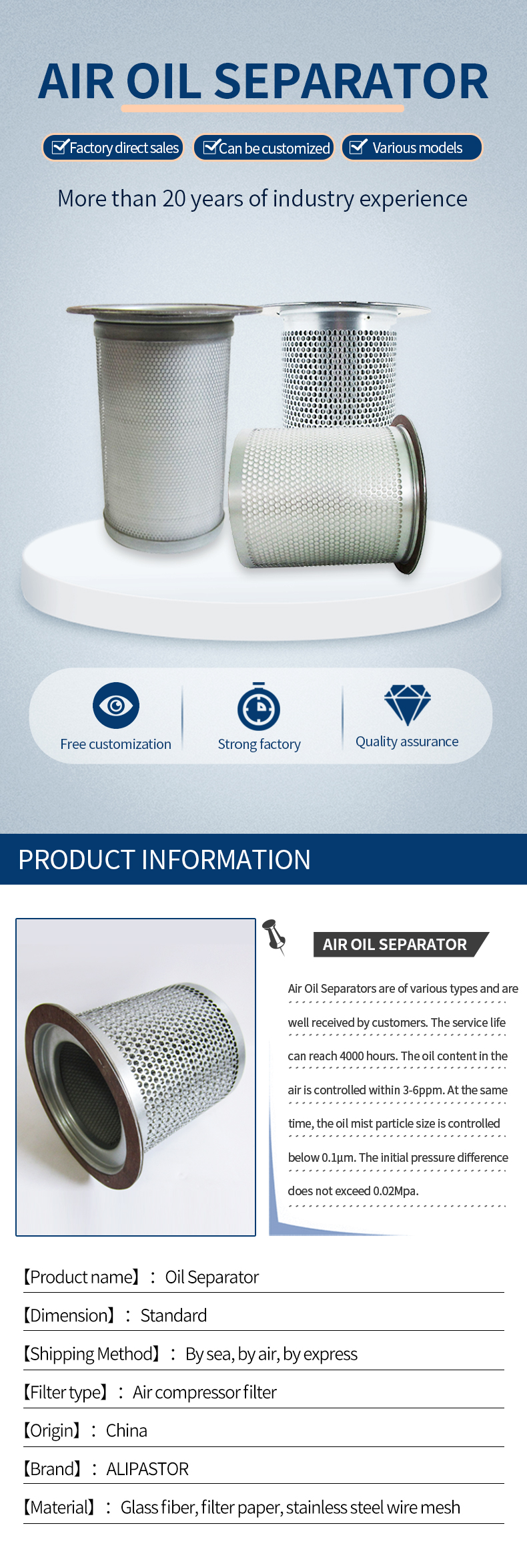
KV350‑009P KV155‑001P KV350‑009P KD285‑007 Oil Gas Separator Filter For Heavy Industrial Screw Compressor Unit
Similar models
| KD390-010 | KD900-043 | KV350-009P |
| KD610-008 | KV195-008P | KV155-001P |
| KD900-018 | KV100-027 | KV350-009P |
| KD285-007 |
Basic Info.
Type | Air Oil Separator | Material | Imported fiberglass |
Warranty | 6 Month | Machinery Test Report | Provided |
Video Outgoing-Inspection | Provided | Place of Origin | Henan, China |
Brand Name | ALIPASTOR | Application | for air compressor |
Product Name | Air Oil Separator | Part Number | KV350‑009P KV155‑001P KD285‑007 |
Keyword | Air Oil Separator | Weight | Standard |
Filtration | 10micron | Color | Customize |
Filtration Grade | 99% | Warranty | 3 Months |
Production Capacity | 1000 PCS/Week |
Product Parameters
Model Number | KV350‑009P KV155‑001P KD285‑007 |
Type | Air Oil Separator element |
Dimension | Standard |
Working Temperature | According to customer's request |
Work Pressure Different | Customized |
Material | Imported fiberglass |
Filter Precision | 10~20μm |
Life span | 2000h |
MOQ | 1 pieces |
Lead Time | Around 5-7 days after order confirmed |
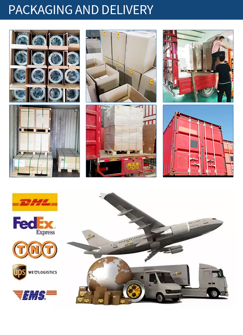
Package | PP bag inside, Inner carton, Export carton outside, or Wooden box as your requirement |
Shipping Method | By sea, by air, by express |
Air-Oil Separation Filter Elements – Models KV350-009P · KV155-001P · KD285-007
Three replacement elements for the final-stage air-oil separation in oil-flooded rotary screw air compressors. KV350-009P is documented as a replacement air/oil separator element , and KV155-001P is cross-referenced to air/oil separator elements in compressor applications . All three models operate on the same coalescence principle: borosilicate micro-glass-fiber media captures oil aerosol from the compressed air discharge, coalesces droplets into larger drops, and returns lubricant to the compressor oil circuit via the scavenge port — discharging clean compressed air with residual oil content of 1–3 mg/m³ (ppm) or below.
How It Works
Air/oil separators operate according to the principle of coalescence . The separation process is effective down to the sub-micron range:
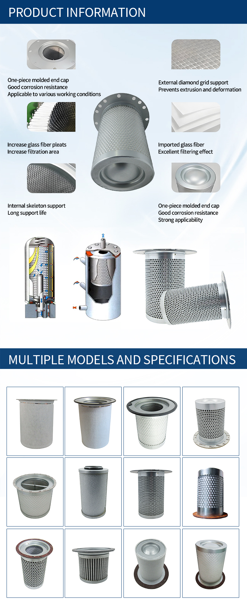
Coalescence – Micro-glass-fibre layers separate drops of oil from the compressed air. Fine oil droplets are pressed through the separation medium; as they pass through, they come together to form larger drops.
Settling – Under the effect of gravity, coalesced droplets sink down through the secondary separation medium on the clean side.
Return – In the standard design, oil flows from the outside to the inside, and the drainage oil is drawn off on the dry side through a centrally positioned pipe running from the base cup of the separator .
The fine separation layer consists of borosilicate glass fibres with defined layer thicknesses; a polyester fabric handles redirection of the oil droplets. The metal parts have an electrically conductive interconnection to reliably transfer any static charges .
Key Features
Borosilicate micro-glass-fiber media – effective separation down to the sub-micron range
Residual oil content: 1–3 mg/m³ (ppm) at nominal flow
Flow resistance: 0.17–0.22 bar (referred to the oil-moistened operating state at nominal volumetric flow and operating temperature)
Max. operating temperature: up to 120 °C
Electrically conductive metal parts – reliable static charge transfer per chemical industry association requirements
Flow direction: Outside → Inside (air); oil returns via centrally positioned scavenge pipe
Flow resistance at nominal load: 0.21 bar @ 100 % relative nominal load (ranges 0.12 bar @ 70 % to 0.30 bar @ 130 %)
Compatible with all standard compressor lubricating oils – mineral-based, synthetic, or partially synthetic
Technical Specifications
Parameter | Typical Value (All Three Models) |
|---|---|
Application | Final-stage air-oil separation in oil-flooded rotary screw compressors |
Media | Borosilicate micro-glass-fibre + polyester fabric redirect layer |
Residual Oil Content | 1–3 mg/m³ (ppm) at nominal flow |
Flow Resistance | 0.17–0.22 bar (nominal); 0.21 bar @ 100 % load |
Max. Operating Temperature | 120 °C |
Flow Direction | Outside → Inside |
Oil Return | Via centrally positioned pipe from base cup |
Static Protection | Electrically conductive metal parts + conductive mounting seal |
Lubricant Compatibility | Mineral, semi-synthetic, and synthetic compressor oils |
Compliance | Operating principle per coalescence separation standard |
📌 Dimensional note: Each model (KV350-009P, KV155-001P, KD285-007) corresponds to a specific dimensional envelope and flow rating for its target compressor platform. Outer diameter, height, scavenge port position, and rated working pressure must be verified against the existing element or compressor service manual before ordering.
Application Guidance
These elements are installed in the separator vessel of:
Stationary and portable rotary screw air compressors
Vacuum pump oil-mist recovery systems
Industrial compressed-air networks requiring low oil carryover
Replacement triggers:
Differential pressure across the separator exceeds the defined limit (refer to 0.17–0.22 bar baseline; escalate replacement evaluation as resistance climbs toward 0.30 bar or beyond at high load)
A zero differential pressure reading indicates the filter core is faulty or the air flow has been short-circuited — replace immediately
Unexplained rise in oil consumption
Visible oil at air outlets downstream
Service life: General replacement time is 3,000–4,000 hours; shortened in poor environments .
Why Correct Selection Matters
⚠️ Over 70 % of a compressor's oil consumption can be driven by a degraded separator. When operating with a clogged or failed separator, oil carryover can reach 20 ppm or higher vs. the normal < 3 ppm — contaminating downstream dryers, pneumatic valves, and finished products, while a 1 psi increase in separator pressure drop raises compressor energy consumption by 0.5 %. Proactive replacement at the correct differential pressure threshold is the single most cost-effective maintenance decision.
Fluid Compatibility
Mineral compressor lubricants – standard compatibility
Semi-synthetic and full-synthetic compressor oils – compatible; the almost binder-free microfibre papers ensure resistance to different lubricant types even at relatively high operating temperatures
Biodegradable oils – verify media compatibility
Installation & Service
Built-in type (most industrial screw compressors):
Stop the air compressor; close the air pressure outlet.
Open the drain valve; confirm the system has no pressure .
Disconnect the pipeline above the oil tank (from the pressure maintaining valve outlet to the cooler); remove the oil pipe.
Remove the fixing bolts of the lid on the oil gas cylinder; take off the upper lid.
Extract the spent separator (disposable — never reuse).
Before installing the new separator, check whether the pressure valve has leakage, whether the oil recovery system is blocked, and whether the one-way valve is damaged .
Clean both sides of the oil tank to ensure the oil separator is grounded; apply grease to the asbestos pad and stick it on the oil flange.
Static protection: Connect the inner metal mesh and the oil tank shell (about 5 staples on upper and lower pads) to prevent electrostatic accumulation from igniting and causing explosion .
When installing the return pipe, insert it to the bottom of the separator, then lift up 1–2 mm to ensure the best effect of returning oil .
Reassemble in reverse order; avoid dirt falling into the oil tank.
External spin-on type:
Stop the compressor; close the air pressure outlet; open the drain valve; confirm zero system pressure .
Remove the old oil separator and replace it with the new air-oil separator.
Monitoring & Maintenance:
Monitor differential pressure monthly using calibrated gauges
Replace when ΔP reaches the defined threshold or when zero ΔP is observed (indicating failure or short-circuit)
In high-dust, high-humidity, or high-load (75–100 % duty) environments, shorten the replacement interval to 3,000–4,000 hours
Gasket installation errors account for 32 % of premature separator failures — always renew seals and torque evenly
Ordering
Specify the exact model (KV350-009P, KV155-001P, or KD285-007) together with:
Host compressor model and rated displacement
Lubricant type (mineral / semi-synthetic / full-synthetic)
Required residual oil grade (standard ≤ 10 ppm / high-efficiency ≤ 5 ppm / ultra-high-efficiency ≤ 3 ppm)
Element outer diameter, height, and scavenge port position
Rated working pressure
Mounting style (spin-on or bolt-in)
Provide a photo or sketch of the existing element for cross-reference if uncertain. Custom configurations can be accommodated.
All values nominal; KV350-009P is documented as a replacement air/oil separator element ; KV155-001P is cross-referenced to air/oil separator elements in compressor applications . All three models use borosilicate micro-glass-fiber coalescing media operating on the principle of coalescence, delivering residual oil content of 1–3 mg/m³ (ppm), flow resistance 0.17–0.22 bar, and max. operating temperature 120 °C . Flow direction is Outside → Inside; oil returns via a centrally positioned scavenge pipe. Metal parts feature electrically conductive interconnection for static dissipation. Compatible with mineral, semi-synthetic, and synthetic compressor oils. General replacement interval is 3,000–4,000 hours (shortened in poor environments); replace when differential pressure reaches the defined threshold or when zero ΔP indicates failure or air flow short-circuit . Dimensional envelope varies by model — verify against the existing element before ordering.





Q2. Is customized filter or OEM available?
A: Yes,just offer your required sepcifications and drawings.
Q3. Can you produce according to the samples?
A: Yes,we can produce by your samples or technical drawings. We can build the molds and fixtures.
Q4.What's the terms of payment?
A: T/T 30% as deposit, and 70% before delivery. We'll show you the photos of the products and packages before you pay the balancing.
Q5.What's your terms of delivery?
A: (1)FOB (2)CFR (3)CIF.
Q6. How about your delivery time?
A: Generally, under MOQ quantity take 5-7 working days after receiving your advance payment. The specific delivery time depends on models and the quantity of your order.
Q7. What's your sample policy?
A: We can supply the sample if we have stock, but the customers have to pay the sample cost and the courier cost at first, and we will refund sample cost in your next order.


