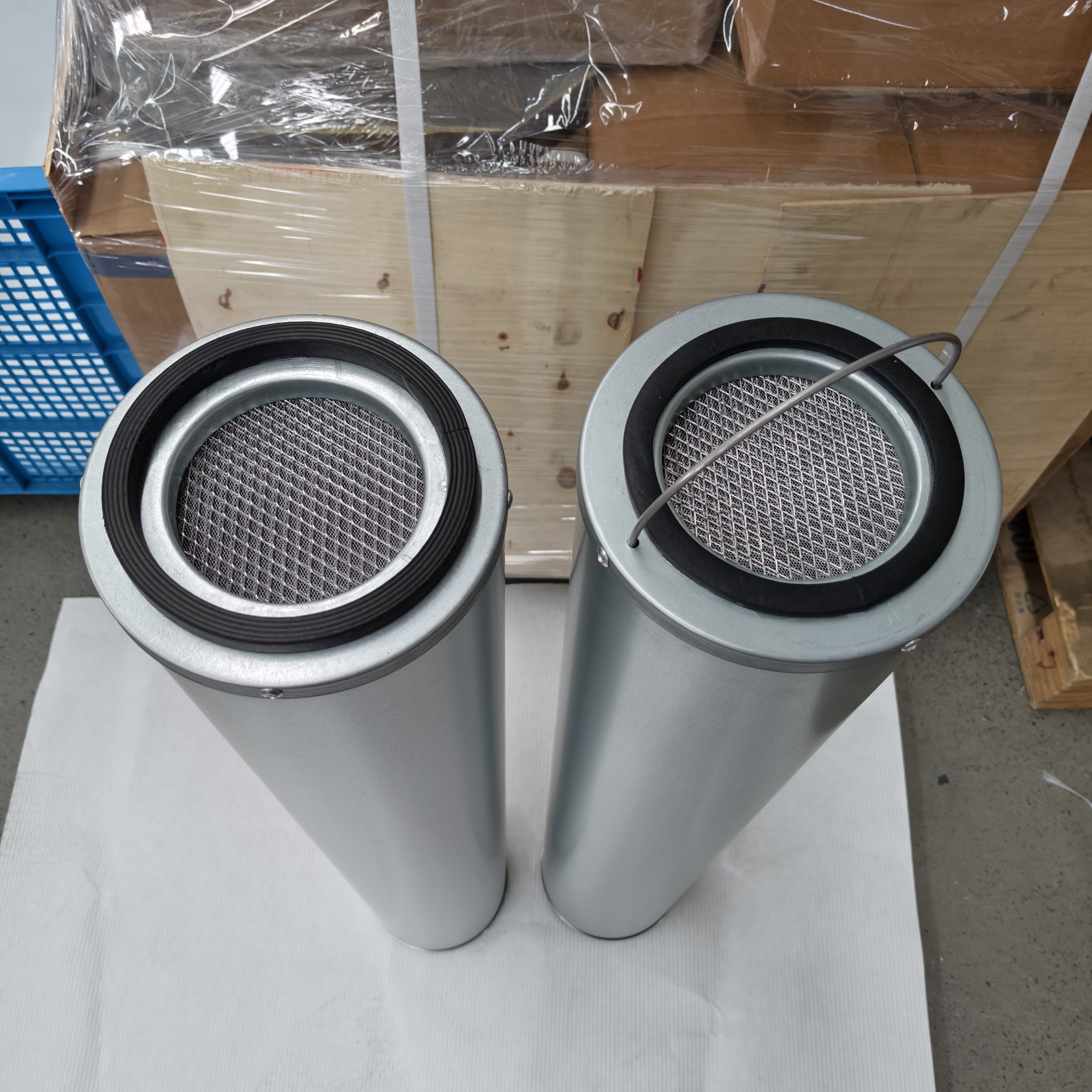
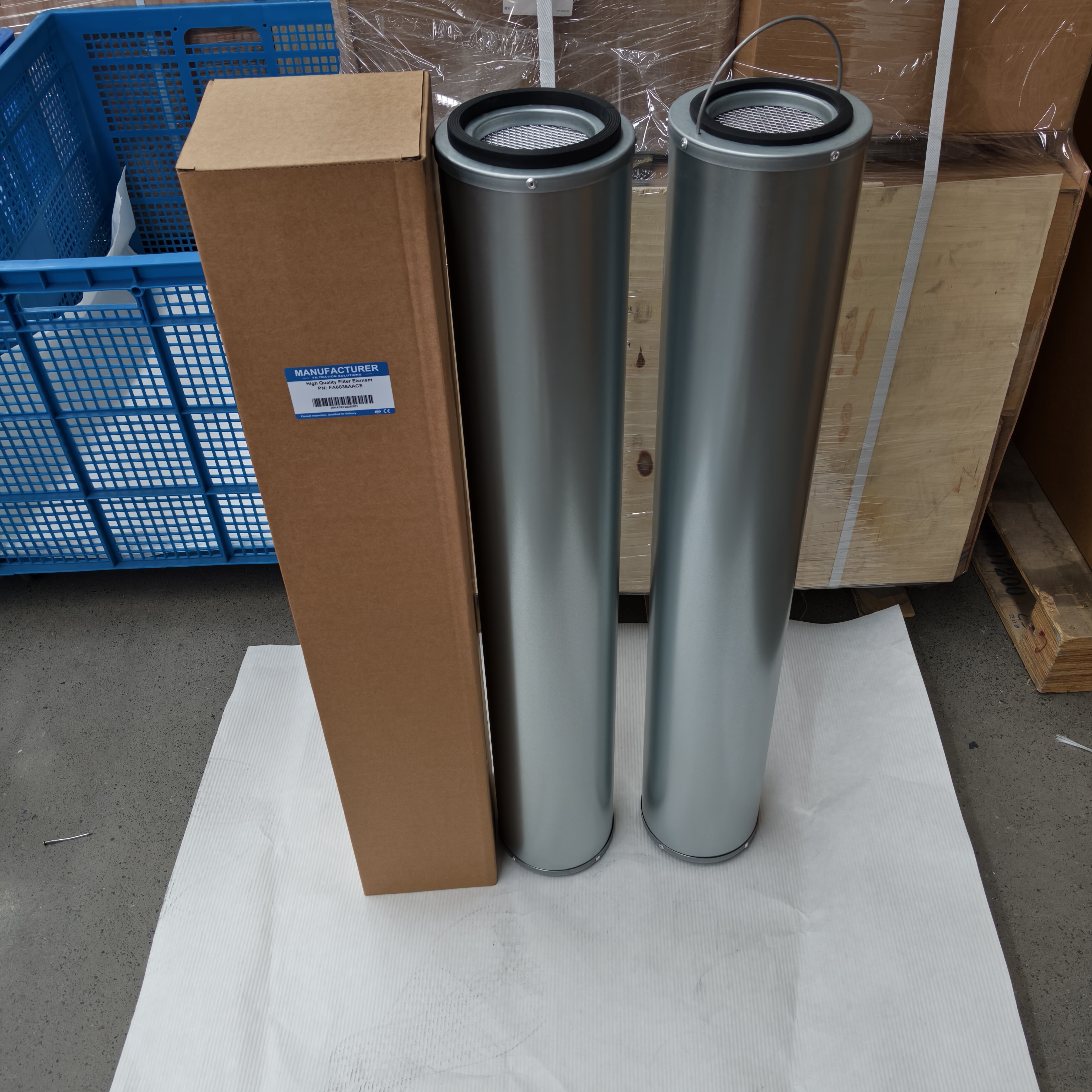
FA6036AACB FA6036AACE Sub-Micron Gas Filtration FA6036AACB FA6036AACE Filter for Gas Turbine Inlet
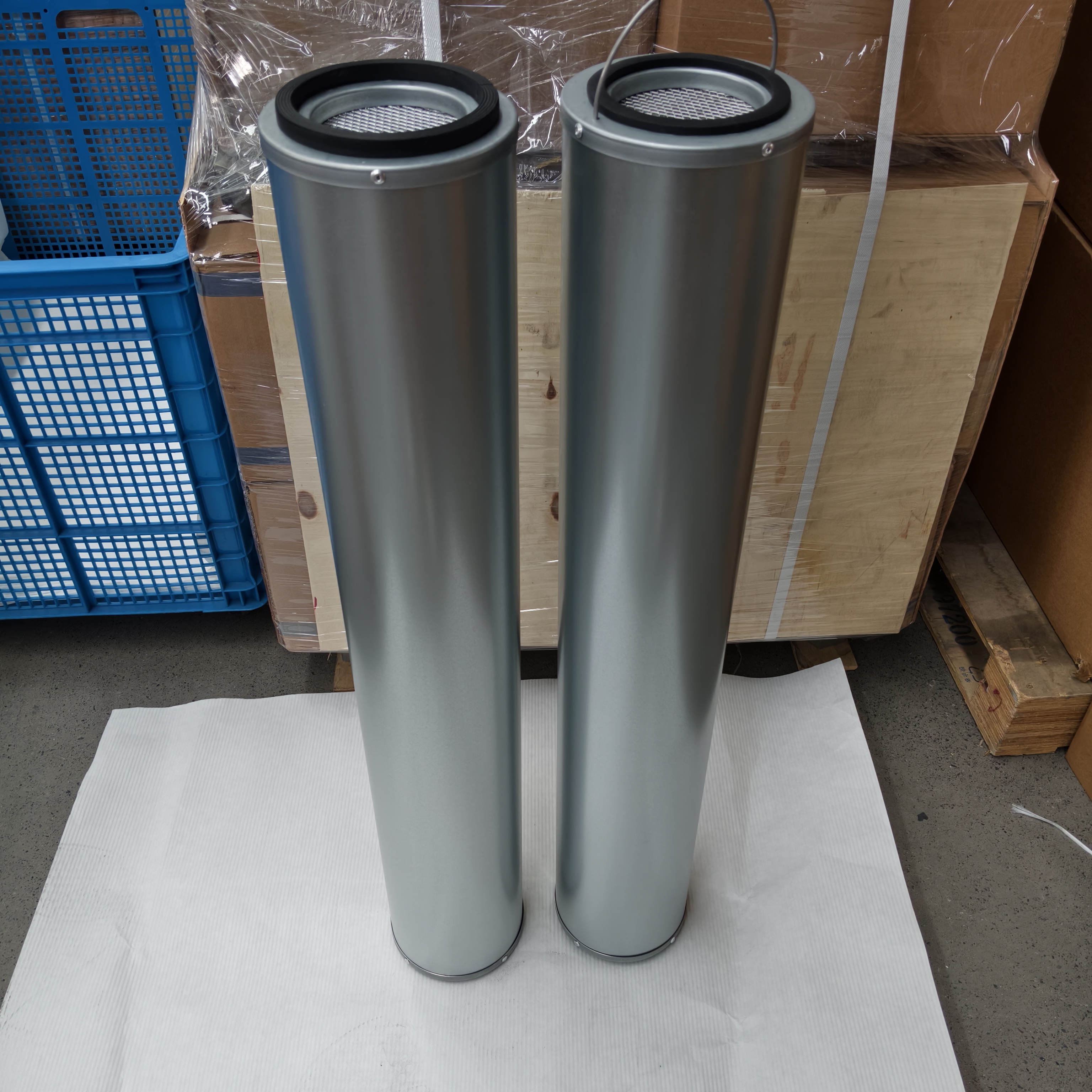
Gas Turbine & Natural Gas Filter Elements – Models FA6036AACB & FA6036AACE
Two high-performance coalescing / particulate filter elements engineered for gas-fired power plant turbine and natural gas filtration systems. These elements perform fine gas filtration, removal of solid particulates, and interception of liquid oil mist and water vapor from compressed natural gas, fuel gas, and turbine lube oil seal gas circuits. They protect downstream turbine blades, combustion chambers, fuel nozzles, and instrumentation from erosion, fouling, and liquid carryover.
Key Features
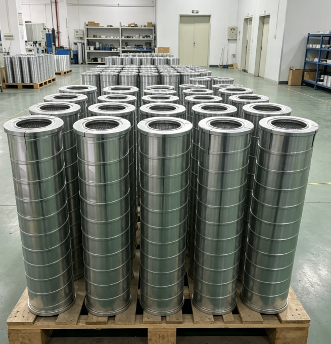
Multi-layer media construction – high-efficiency microfiber glass or synthetic media with drainage layers for liquid coalescence
Solid particulate removal down to 0.3–1 µm with ≥ 99.97 % efficiency (DOP test equivalent)
Liquid aerosol interception – coalesces oil mist and water droplets into bulk liquid that drains to sump
Low initial differential pressure – minimizes parasitic pressure loss in fuel gas supply
High dirt-holding capacity – extended service interval between replacements
Corrosion-resistant core and end caps – stainless steel or coated carbon steel for sour gas compatibility
Temperature range – -20 °C to +100 °C (continuous)
Seal material – NBR or FKM (fluorocarbon) for natural gas / hydrocarbon service
Test standards – ISO 8573-1 (compressed air purity), ISO 12500 (coalescing filter performance), ASTM D2986 (DOP efficiency)
Technical Specifications
Parameter | FA6036AACB | FA6036AACE |
|---|---|---|
Application | Natural gas / fuel gas coalescing & particulate filtration | Natural gas / turbine seal gas fine filtration |
Media | Microfiber glass with drainage layer | Microfiber glass with enhanced coalescing layer |
Particulate Removal | ≥ 99.97 % @ 0.3 µm | ≥ 99.97 % @ 0.3 µm |
Liquid Aerosol Removal | ≥ 99.5 % (oil mist & water fog) | ≥ 99.9 % (oil mist & water fog) |
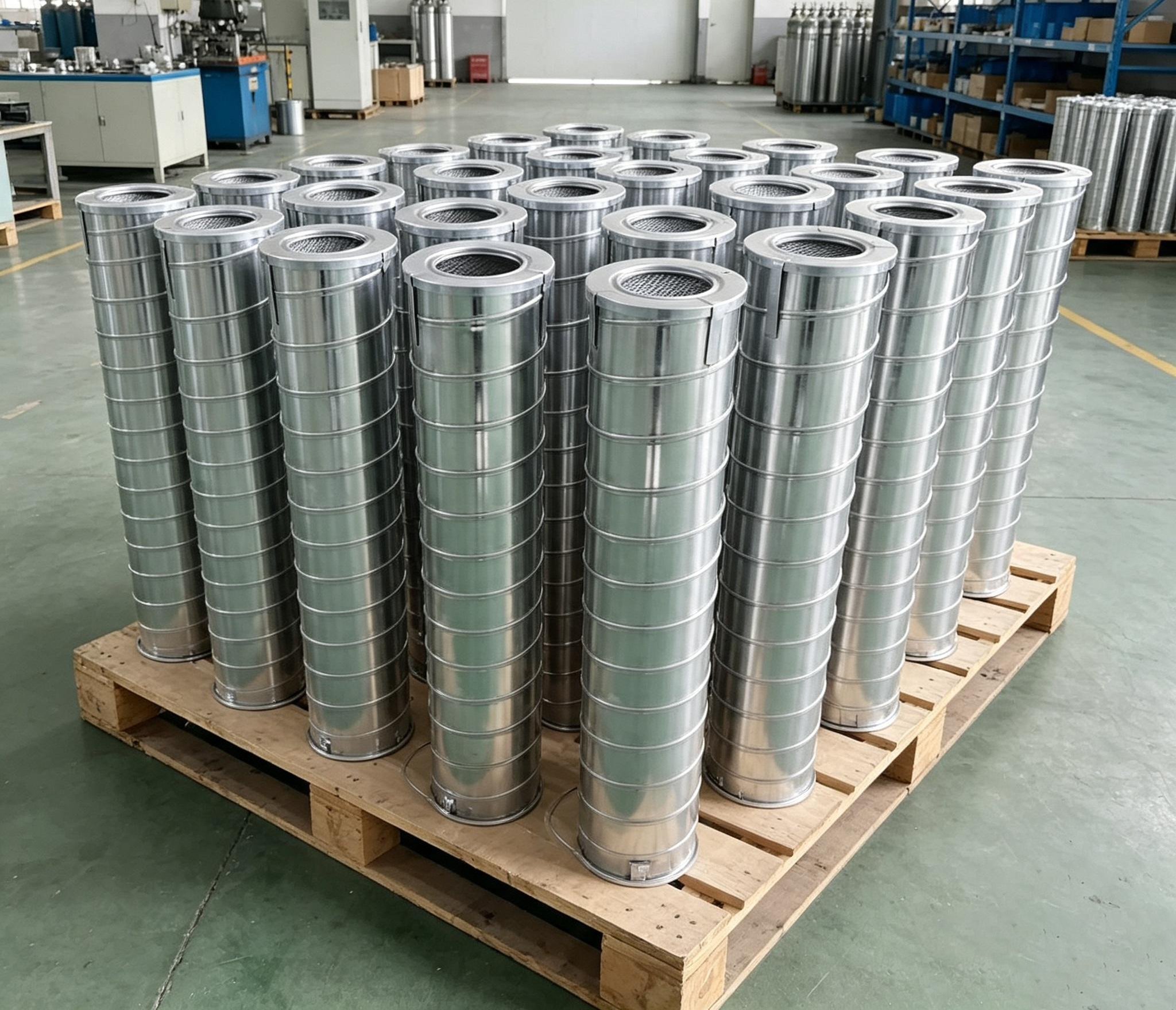
Dimensions (OD × ID × H) | Configurable per housing* | Configurable per housing* |
Max. Operating Pressure | Up to 105 bar (1500 psi) | Up to 140 bar (2000 psi) |
Max. Differential Pressure | 3.5 bar (50 psi) | 3.5 bar (50 psi) |
Operating Temperature | -20 °C to +100 °C | -20 °C to +100 °C |
Seal Material | NBR (FKM optional) | FKM (standard) |
Flow Direction | Outside → Inside | Outside → Inside |
Drainage | Automatic (integrated drain layer) | Automatic (dual drain layer) |
Test Standard | ISO 8573-1 / ISO 12500 / ASTM D2986 | ISO 8573-1 / ISO 12500 / ASTM D2986 |
* Confirm exact OD, ID, and height against existing element or housing drawing.
Application Guidance
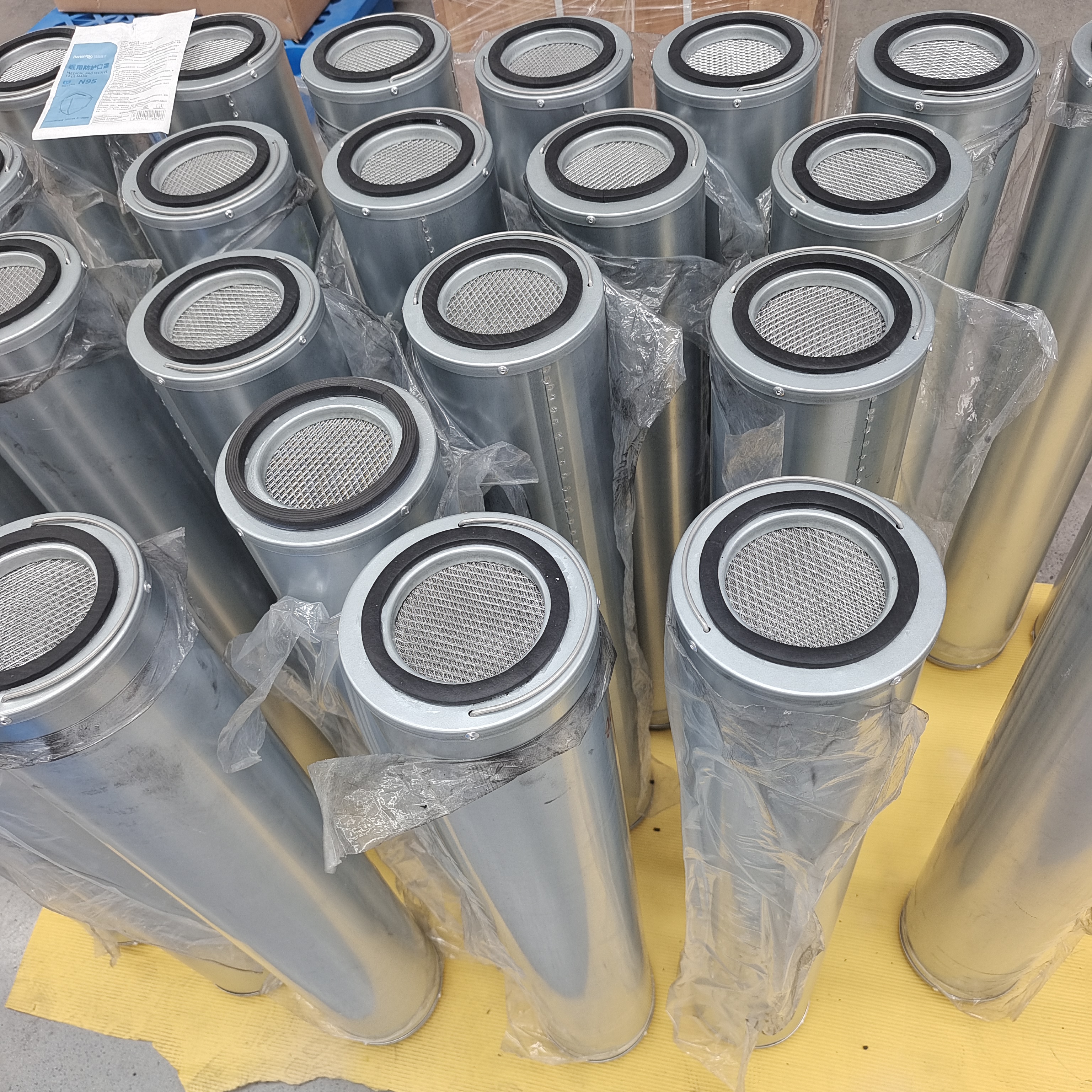
Both elements are deployed in gas-fired combined-cycle power plants, simple-cycle gas turbines, and natural gas compression stations:
FA6036AACB – Primary fuel gas coalescer / particulate filter located upstream of the gas metering skid and turbine fuel gas module. Removes pipeline debris, rust, and liquid hydrocarbons / water condensate to protect fuel control valves and combustion hardware.
FA6036AACE – High-efficiency final-stage filter / coalescer positioned immediately ahead of the turbine fuel gas manifold. Provides ultra-low liquid carryover (< 0.01 ppm w/w) and sub-micron particulate removal for sensitive fuel nozzle and combustion dynamics stability.
Also applicable to:
Turbine bearing seal oil degassing / gas vent filtration
Hydrogen-cooled generator seal gas purification
Instrument air backup for pneumatic actuators
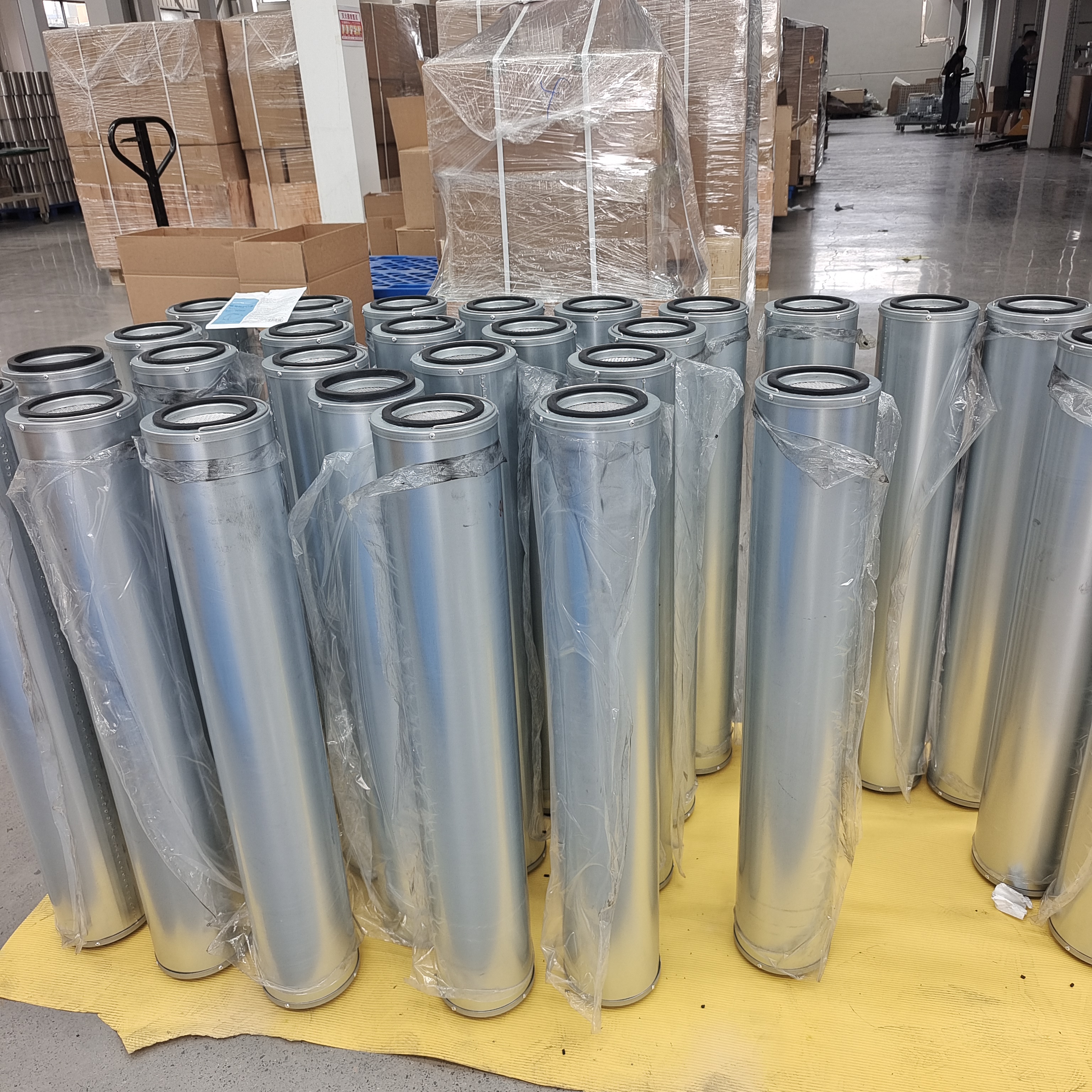
Why Filtration Matters in Gas Turbine Systems
Liquid carryover in fuel gas causes flame instability, increased NOx emissions, hot-gas-path corrosion, and fuel nozzle coking. Solid particulates erode turbine blades and plug fuel metering orifices. A properly selected coalescing filter element with ≥ 99.97 % efficiency at 0.3 µm and ≥ 99.5 % liquid removal ensures:
Stable combustion dynamics
Extended turbine hot-section life
Reduced maintenance frequency for fuel gas skid components
Installation & Service
Depressurize the filter vessel completely; vent to flare or atmosphere.
Open the vessel closure; withdraw the spent element by its center tube.
Inspect the vessel interior, drain port, and seal surfaces.
Seat the new element – confirm flow direction (Outside → Inside) and proper O‑ring placement.
Close the vessel; torque bolts evenly per manufacturer specification.
Slowly repressurize; check for leaks at all flanges and the drain valve.
Monitor differential pressure gauge – replace when ΔP reaches 1.0–1.5 bar or as indicated by the operator's maintenance schedule.
Coalescing elements are disposable – never attempt to clean or reuse.
Ordering
Specify FA6036AACB or FA6036AACE together with:
Dimensional envelope (OD, ID, overall length)
Required filtration efficiency (particulate & liquid removal)
Operating pressure and temperature range
Seal material (NBR / FKM)
Drain connection type (automatic float / manual ball valve)
Provide the existing element's dimensions or the host vessel model for cross-reference confirmation. Custom media grades and end‑cap configurations are available on request.
All values nominal; FA6036AACB and FA6036AACE are gas turbine / natural gas coalescing filter elements with microfiber glass media, ≥ 99.97 % particulate efficiency at 0.3 µm, ≥ 99.5 % liquid aerosol removal, up to 140 bar operating pressure, and full compliance with ISO 8573-1, ISO 12500, and ASTM D2986. Confirm housing dimensions, fluid composition, and operating conditions before installation.
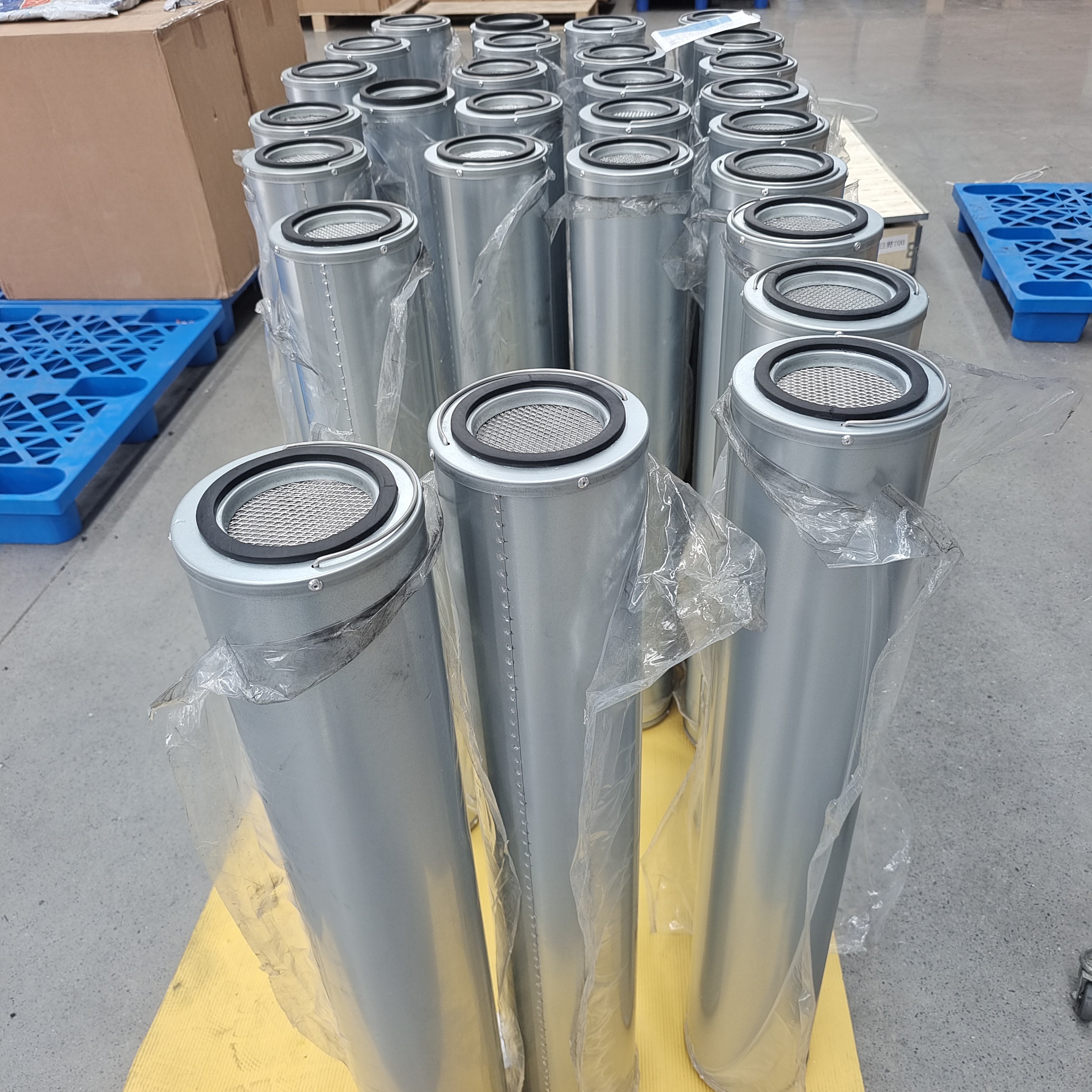
Recommended Related Models:
FA6036AACE | FA614-1A |
FA6036AACB | FA614-2A |
FA6036AACC | FA614-3A |
FA6036AACD | FA614-5A |
FA6024AACE | FA628-1A |
FA6024AACB | FA628-2A |
FA6024AACC | FA628-3A |
FA6048AACE | FA628-5A |
FA6048AACB | FA644-1A |
FA6048AACC | FA644-2A |
FA644-3A | |
FA644-5A |